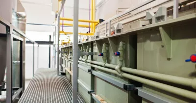
Optimizing LEV Systems for Safe Electroplating Environments
August 03, 2026
August 03, 2026
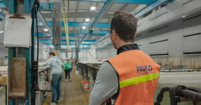
Ventilation in an electroplating facility is not an amenity, it is a legal requirement and a direct determinant of worker health. Local exhaust ventilation (LEV) systems are the primary engineering control that keeps hazardous mists, fumes, and vapors from reaching the breathing zone of your operators. Getting them right requires understanding a layered regulatory framework, making informed engineering decisions, and maintaining systems with the same discipline you apply to bath chemistry.
This article walks through the key technical and regulatory considerations for optimizing LEV systems in electroplating environments.
Why LEV Is Non-Negotiable in Electroplating
Electroplating baths generate hazardous airborne contaminants as a byproduct of the electrochemical process. Acid mists from zinc and nickel baths, hexavalent chromium aerosols from traditional chrome plating lines, and alkaline vapors from pre-plate cleaning tanks all pose significant inhalation risks.
LEV systems capture contaminants at the source before they disperse into the room air. This is the engineering control hierarchy at its most effective: eliminate the exposure pathway before it reaches the worker.
For facilities with hexavalent chromium operations, this is particularly critical. OSHA 29 CFR 1910.1026 establishes that hexavalent chromium is a confirmed human carcinogen, and the regulatory burden for Cr VI exposure monitoring, medical surveillance, and LEV performance verification is substantial.
LEV System Types: Matching Configuration to Application
LEV systems for electroplating are not a single category, they vary considerably based on tank geometry, chemical aggressiveness, and required capture efficiency. The three primary configurations are:
1. Pull-Only (Exhaust-Only) Systems:
A single exhaust hood or slot captures contaminants from one side of the tank. Best suited for narrow tanks, lower-toxicity baths, and operations where face velocities can be maintained without cross-drafts. Simpler to design and install, but more sensitive to disruption from operator movement and ambient air currents.
2. Push-Pull Systems:
A supply air plenum on one side of the tank pushes a low-velocity air curtain across the bath surface toward an exhaust slot on the opposite side. This configuration is highly effective for wide tanks where a pull-only system would require impractically high face velocities. Push-pull systems significantly reduce the total exhaust volume required while maintaining excellent capture efficiency.
3. Total Enclosure Systems:
The tank is enclosed within a ventilated cabinet or booth, analogous to a paint spray booth. Total enclosure provides the highest degree of containment and is required for the most hazardous operations (e.g., hexavalent chrome tanks subject to NESHAP limits). The tradeoff is reduced operator accessibility during normal production.
The correct system type depends on bath toxicity, tank dimensions, operating temperatures, production throughput, and the specific PEL or emission limit that must be achieved.
Airflow Requirements: CFM, Face Velocity, and System Sizing
LEV performance is quantified in terms of air volume (cubic feet per minute, CFM) and face velocity (feet per minute, FPM), the velocity of air entering the hood opening.
Face velocity requirements for electroplating tanks typically range from 75–150 FPM for slot hoods, depending on:
The chemical toxicity and volatility of the bath
The tank temperature (higher temperature = more vapor generation)
The presence of air turbulence from operators, equipment, or HVAC
For push-pull systems, the supply plenum velocity should be designed to create a coherent air curtain across the bath surface without turbulence that could carry mist upward into the workspace.
Blower and ductwork sizing must be calculated to deliver the required CFM at the design face velocity, accounting for:
Total hood opening area (square feet)
System static pressure losses through ductwork, fittings, and any treatment equipment (scrubbers)
Fan curve performance at the operating static pressure point
Undersized blowers are a common deficiency found in LEV inspections. Over time, duct corrosion, damper drift, and accumulated deposits increase system resistance, causing airflow to drop below design levels even when the fan appears to be running normally. Regular performance verification is essential.
Materials Selection: Corrosion Resistance in the Duct System
Electroplating vapors are corrosive to most common construction materials. Carbon steel ductwork will corrode rapidly when exposed to acid mists from zinc, nickel, or chrome plating baths.
Here are the recommended duct materials based on bath chemistry:
Acid zinc, acid copper, chromic acid: PVC, polypropylene, or fiberglass reinforced plastic (FRP)
Alkaline zinc, alkaline cleaners: Polypropylene or coated carbon steel
Nickel sulfamate, nickel chloride: PVC or FRP
Hexavalent chrome: FRP with chemical-resistant lining
Hood faces, blower housings, and fasteners should be specified in compatible materials to prevent premature failure that reduces LEV effectiveness and creates maintenance liability.
Fans selected for corrosive service must use corrosion-resistant impellers (FRP or coated aluminum) rather than standard carbon steel. A corroded or damaged impeller that fails in service can result in an immediate LEV outage, triggering OSHA exposure concerns and potential production shutdown.
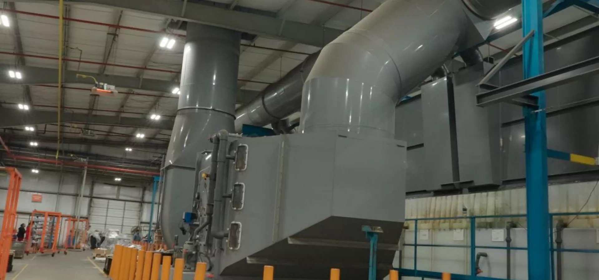
Scrubbers and Stack Requirements
When the exhaust air from an LEV system contains concentrations of hazardous pollutants that exceed EPA emission limits, a wet scrubber must be installed before the exhaust exits the building.
For chrome plating operations subject to NESHAP, packed-bed scrubbers or mist eliminators are required to reduce Cr VI aerosol concentrations to compliant levels prior to stack discharge. Scrubber efficiency must be verified through periodic stack testing.
When a scrubber is not required — for lower-toxicity chemistries that do not trigger NESHAP thresholds — the exhaust stack must still be designed to prevent re-entrainment of contaminants back into the facility or neighboring areas. Stack height and discharge velocity are calculated based on local meteorological data, surrounding building geometry, and the dilution factor required to achieve acceptable ground-level concentrations.
Fresh Air Replacement: Makeup Air Systems
An LEV system that exhausts large volumes of air from a facility creates a negative pressure inside the building unless replacement (makeup) air is supplied. Failure to address this results in:
Reduced face velocity at tank hoods as the building draws in uncontrolled infiltration air from cracks, doors, and gaps
Cold drafts in winter months that reduce worker comfort and increase heating costs
Difficulty opening doors and creating uncontrolled air paths
Makeup air units supply conditioned replacement air at a volume approximately equal to the total LEV exhaust rate, maintaining neutral or slightly negative pressure inside the electroplating area. Makeup air should be introduced at a location and velocity that does not disrupt LEV capture — typically from the ceiling level, directed away from tank hoods.
In most climates, makeup air should be tempered (heated or cooled) to avoid introducing extreme temperature differentials that affect bath temperature stability or worker conditions.
A Systemic Approach to LEV Optimization
Optimizing an LEV system is not a one-time project, it is an ongoing discipline that parallels bath chemistry management. The key elements of a robust LEV management program include:
Baseline performance documentation: Air velocity measurements at all tank hoods, recorded as the system commissioning standard
Periodic airflow verification: Quarterly or semi-annual measurements to confirm velocities remain within design parameters
PEL monitoring: Regular personal dosimetry measurements correlated with operational conditions
Preventive maintenance: Duct inspection, blower bearing checks, scrubber media replacement, and damper position verification on a defined schedule
Change management: Formal evaluation any time a new bath chemistry, tank addition, or production rate change is introduced that could affect LEV loading
PAVCO®'s technical service team works alongside metal finishing professionals to address not just chemistry, but the full suite of process conditions that determine whether a plating line performs safely, reliably, and profitably. As a NASF Premier Partner and ISO 9001:2015-certified organization, PAVCO® brings the same rigor to its technical partnerships that it brings to its chemistry development.
If you are reviewing your LEV systems, modernizing your chrome plating line with trivalent chromium technologies, or evaluating compliant chemistry options that reduce your regulatory burden while maintaining performance, contact a PAVCO® Technical Service Representative today.
- Share:
-
![Facebook]()
-
![Twitter]()
-
![Mail]()


Related Articles

IT’S HOW YOU FINISH
We’re a developer and supplier of chemistries for the metal finishing industry since 1948.
In PAVCO, we develop products and deliver services of the highest quality at a reasonable cost.